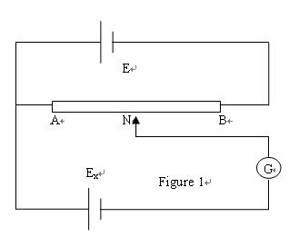
Potentiometer is used frequently to precisely measure the DC voltages or power potentials with null-balancing theory. It requires no advanced (electronic) circuitry or sensitive devices like transistors or vacuum tubes, but it does provide such features as accurate measurement, convenient operation and reliable results, etc.. Indirectly it can also be used to precisely measure the current, resistance, and to calibrate types of precision devices. The purpose of this experiment is to learn the theory of Potentiometric voltage measurement, master the operation and mechanism of potentiometer, know how to measure the potential and internal (lead-to-lead) resistance of a DC battery. Theory 1. Potentiometric: Since voltmeters are always connected in parallel with the component or components under test, any current through the voltmeter will contribute to the overall current in the tested circuit, potentially affecting the voltage being measured. A perfect voltmeter has infinite resistance, so that it draws no current from the circuit under test. However, perfect voltmeters only exist in the pages of textbooks, not in real life! A final, and ingenious, solution to the problem of voltmeter loading is that of the potentiometric or null-balance instrument. It requires no advanced (electronic) circuitry or sensitive devices like transistors or vacuum tubes, but it does require greater technician involvement and skill. In a potentiometric instrument, a precision adjustable voltage source is compared against the measured voltage, and a sensitive device called a galvanometer is used to indicate when the two voltages are equal. In some circuit designs, a precision potentiometer is used to provide the adjustable voltage, hence the label potentiometric. When the voltages are equal, there will be zero current drawn from the circuit under test, and thus the measured voltage should be unaffected. The galvanometer is a sensitive device capable of indicating the presence of very small current. An electromechanical meter movement is used in the galvanometer. It has a spring-centered needle that can deflect in either direction so as to be useful for indicating a voltage of either polarity. As the purpose of a galvanometer is to accurately indicate a condition of zero voltage, rather than to indicate any specific (nonzero) quantity as a normal voltmeter would, the scale of the instrument used is irrelevant. Null detectors are typically designed to be as sensitive as possible in order to more precisely indicate a "null" or "balance" (zero voltage) condition. To operate this instrument, the technician would manually adjust the output of the precision voltage source until the null detector indicated exactly zero, and then note the source voltage as indicated by a voltmeter connected across the precision voltage source, that indication being representative of the measured voltage.
UAN=Ex.
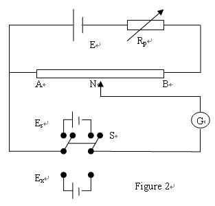
The voltmeter used to directly measure the precision source need not have an extremely high Ω/V sensitivity, because the source will supply all the current it needs to operate. So long as there is zero voltage across the galvanometer, there will be zero current between points N and S, equating to no loading of the divider circuit under test. 2. Potentiometer Potentiometers are variable voltage dividers with a shaft or slide control for setting the division ratio. They are manufactured in panel-mount as well as breadboard (printed-circuit board) mount versions. Any style of potentiometer will suffice for this experiment. The potentiometer in this lab uses an 11m wire to replace the slide-resistance AB in figure 2. The construction of the potentiometer is as shown in figure 4. Resistance AB is evenly divided into 11 parts, each with 1m in length.
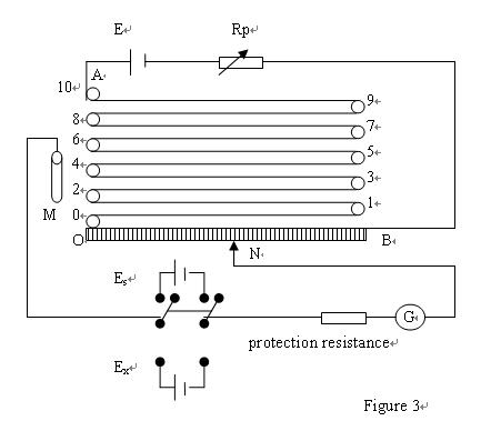
According to the labeling U0 between AB and the length of wire , preset positions M, N as M’ and N’ so that . For a commonly used standard battery, Es=1.01860V. Connect Es and adjust Rp to balance the circuit, so Keep E and Rp unchanged, connect S to Ex and adjust M, N to balance the circuit again: Therefore, Let the resistance wire length lx, ls correspond to RMN and RM’M’ respectively, then U0 is the voltage between the unit length wire. Procedures Setup the circuits according to figure 3. E is the DC power. In building the circuits, take care of the polar of E, Ex and Es. 1. Labeling Measure and record the resistance RAB with a multimeter. Plug M into point 5, N at around 66cm, protection resistance to “rough”, connect switch to Es. Adjust Rp to zero galvanometer; protection resistance to “middle”, adjust Rp to zero galvanometer; protection resistance to “fine”, adjust position N to zero galvanometer. Now the distance between M, N is ls. Record it. Calculate and record U0=Es/ ls, here Es is the potential of the standard battery. Calculate and record UAB. Record the output voltage of DC power. 2. Measurement of battery potential Measure the battery potential with a multimeter. Use U0 to estimate lx. Adjust M,N to have the distance of lx. Connect switch to Ex, change the position of protection resistance from “rough”, “middle” to “fine” to zero the galvanometer individually. Find the exact lx and Ex (U0 lx) ******************************************************************** Potentiometric Voltage Measurement Names:
|